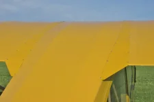
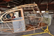
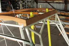
Wing gap covers

New2Champs

Member
Joined
Aug 18, 2026
Messages
8
Location
California
I am returning to work on my Champ 7 AC after a long illness. I think I have all the wing gap covers but I don’t remember if there is a single drawing with the numbers showing how they fit together. I have parts from multiple Champs and none of them have the same dimensions. Please let me know if there’s a single drawing with all the information available or another way to identify the parts and how they fit together. Thanks
 
There's a drawing which shows the part numbers for all the individual pieces in your service manual. Each part has its own separate drawing, left and right are the same, just flipped. The front piece always slides over the next piece behind it all the way to the aft piece. The last short top piece has a bend in the bottom of it and captures the aft end of the last bottom piece.
Make your pieces to fit your plane, there may be small variations between different planes.
Be careful with those screws so they don't go into the spars.
 
Thank you for the information. I apologize in advance for all the questions, but I have Wing Gap cover parts for several airplanes (multiple paint schemes), and only one part (3-451) matches the dimensions from the blueprint. The airplane was taken apart in 1999; I was not there; I started this as a basket case, and I am not sure how to verify the left from the right part.

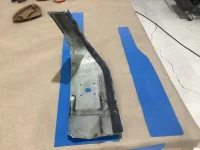
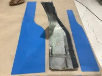
Part # 3-451 (top-first) is the first Wing Gap part. Does the straight end go against the fuselage or the wing? There is a large bend in the part, so I suspect it is bent around the front of the leading edge, but I am not sure where the ends of the part should end on the top and bottom of the wing. The second Wing Gap is #3-452 (top-middle), a straight, flat part that appears to have been attached mostly with silicone adhesive. Is this the way to avoid screws into the spar? The third top Wing Gap part is #3-453 (top-end). I believe this is the part with the fold that you mentioned in your post. Is this all the wing Gap Parts on the top? The second Wing Gap is #3-455 (bottom middle), and it has a flange. How does the flange fit? When lining up #3-453 (top) and #3-455 (third bottom), do they completely cover the end of the wing? Thanks in advance for your help.
 
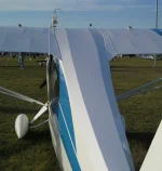
Word of warning I’m currently reassembling by 1977 GCBC I ordered all knew a wing gap seals and one on the far left was the first one they sent me, it’s actually for a decathlon, the one on the far right is what they sent me to replace it for 7 GCBC in the one of them metal with the aluminum showing it what came off the airplane. These are all for the leading edge that go around the windshield, which is the rubber part straight edge goes to the outside towards the wind. A little bit of a curve follows the roof line back. Screw holes go into the inner rib on the wing. I hope this helps you And good luck.
 

Attachments

  • IMG_2624.webp
    IMG_2624.webp
    1.1 MB · Views: 34
  • IMG_2625.webp
    IMG_2625.webp
    1.2 MB · Views: 32
I am returning to work on my Champ 7 AC after a long illness. I think I have all the wing gap covers but I don’t remember if there is a single drawing with the numbers showing how they fit together. I have parts from multiple Champs and none of them have the same dimensions. Please let me know if there’s a single drawing with all the information available or another way to identify the parts and how they fit together. Thanks
Where are you located?
 
Look at these photos.
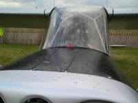
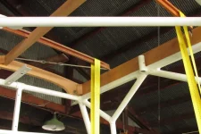
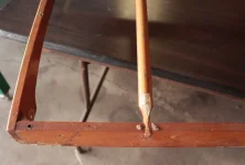
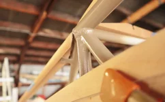
The LE piece wraps around the LE and ends about where the front spar is. It has a rubber molded edge attached so the metal doesn't wear against the windshield. pic 1
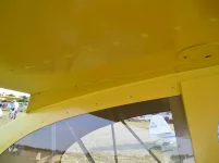
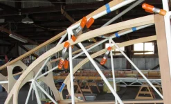
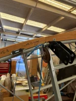
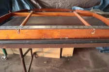
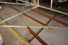
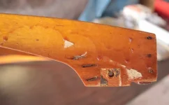
Here's the two TE pieces, the bottom fits into the folded edge of the top piece. See that there's an angle on the very TE.
Pic 2 and 3
The two bottom pieces also have a bent edge about 85 degrees and it just sits against the fuselage, the screws are only on the butt rib, none into the fuselage. All other pieces have screws in the rib side and in the wood fairing in the fuselage.
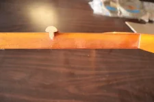
As for screws they should be #4 x 1/4" long, unless they're enlarged from years of use. Be careful using larger and longer screws where the front and rear spar are. You don't want to screw into any spars.
 

Attachments

  • Oshkosh 05 036 (1024x766).webp
    Oshkosh 05 036 (1024x766).webp
    87.9 KB · Views: 22
  • Oshkosh 05 129 (1024x766).webp
    Oshkosh 05 129 (1024x766).webp
    44.2 KB · Views: 21
  • IMG_6395 (1024x683).webp
    IMG_6395 (1024x683).webp
    19.4 KB · Views: 20
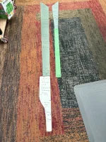
Bartman, I am based in Southern California, Cable Airport EAA 448. Thanks for everyone's help; the pictures made the placement of the wing gap covers understandable. I laid the wing gap parts down and labeled how they fit on the wing and to the fuselage. You may not be able to see the wing gap parts, but I wrote the part number and how they fit together with a grease pencil. After reading Bruce's post, I decided to see if the wing gap parts fit. I have wings that need to be rebuilt, so I taped the wing gap parts on the wing, and they seem to be good based on the distance to the fuselage. The last two top wing gap portions (#3-452 & #3-453) were made as one piece for me by Ron at Rainbow Flying Service. I have found that Ron provides quality products and service. I documented cautions about screw placement, size, and rubber molding on the drawings so I do not forget when it comes time to attach the wings to the fuselage. However, I do not recognize the rubber-molded edge that fits against the windshield in my parts inventory. Is there a part number for that molded edge? I also noted the smooth lines from the top of Champdrivers Aeronca. After I finish with my inventory, I plan on returning to fitting the stringers and completing the upper deck. Are there dimensions with the contour to ensure the upper deck height will flow with the wings?
 

Attachments

  • Wing Gap Cover Layout.webp
    Wing Gap Cover Layout.webp
    107.2 KB · Views: 14
Don't quote me but PN 05-01300 may be the one that fits against the windshield at AS & S.
If you have a spare rib hold it against the fuselage to match the curvature of the wing to the upper cabin wood pieces.
After the wing is mounted then final match and drill the fairings to the fuselage.
I've made all new wood stringers and bulkheads for my plane, if you need any kind of help there.
The photos I took are from Oshkosh and other fly-ins and are not my plane.
Post a few photos to show us what you have.
 

Attachments

  • IMG_3658 (1024x683).webp
    IMG_3658 (1024x683).webp
    127.3 KB · Views: 12
Thanks for the photo Champdriver. Details showing how stringers #1-2366 fit to the frame in front would be immensely helpful (a lot of twisting and bending from the last bulkhead 7-455 to fit to the frame). It would also help to know the height of #3-525 (upper assembly) above the frame, as that will tell me how much material needs to be removed so the wings fit. Photos of how you taper wood parts together will help me to visualize how everything flows together. Finally (I think) is how high above #3-525 (upper assembly) the stringers #1-2679 should be. I will get Ms. Sunshine (N2281E) ready for her photo debut and post pictures soon. Thanks for all the help.
 
Do you have patterns or drawings to work from in making new stringers and formers. If not then if you join the National Aeronca Assoc they will send you a CD with many but not all the drawings from the factory. Part numbers are drawing numbers.
I used the old parts off the plane as patterns to make new parts and routed my own mushroon stringers.

Let's start with the top two center 'T" or mushroom head stringers over the cabin. The front edge sits down flush with the front side to side former. The first few inches of the mushroom head is sanded down so it fits flush. I used a 6" stationary belt sander to do this and it worked perfectly.
Moving aft, the stringers straight part sits down in the next formers and just the mushroom head alone sits above the former. It's like that all the way to the tail.
As for the next two mushroom stringers that go from the aft TE to the tail, there shouldn't be any need to twist them, bending yes, twist no. On the front end you sand down the inside to a taper so it lays down and fits flush with the TE on the cabin. pic 3
As for bending, get a PVC pipe with a cap on it and fill with water and let them soak a few hours. Then install and hold them down with something and let dry for a day or two, whatever you think.
On the front center two, I used rachet straps and pulled them down a little at a time. Every so often pull them down a little more without breaking the cabin formers.
On the two mushroom stringers on the belly you'll have to soak and bend them too.
The two side stringers from the aft end of the window and the door, and the center belly stringer are simple 1/4" x 3/4" spruce.
 

Attachments

  • IMG_9963 (1024x683).webp
    IMG_9963 (1024x683).webp
    85.6 KB · Views: 14
  • IMG_9965 (1024x684).webp
    IMG_9965 (1024x684).webp
    81.1 KB · Views: 14
  • IMG_9944 (1024x624).webp
    IMG_9944 (1024x624).webp
    96.2 KB · Views: 17
Last edited:
The pictures help a lot. As you can see from the attached photos, I was not able to marry the outside stringer above the window frame, and I will need to start from scratch. I do have the Aeronca Blueprint disk. Is there a height above the frame the upper deck should be to flow into the wings? The upper deck is flat and sits on top of a round tube. Did you sand a half-round in the bottom of the upper deck so it sits flat on the frame?
 

Attachments

  • Right side Upper deck to window fit.webp
    Right side Upper deck to window fit.webp
    47.4 KB · Views: 12
  • Right side stringer split fit to window.webp
    Right side stringer split fit to window.webp
    75.1 KB · Views: 13
  • Right Upper Deck fit.webp
    Right Upper Deck fit.webp
    75.9 KB · Views: 14
  • Close up stringer entering upper deck.webp
    Close up stringer entering upper deck.webp
    69.8 KB · Views: 13
  • Left side stringer to upper deck fit.webp
    Left side stringer to upper deck fit.webp
    68.8 KB · Views: 16
Photo 1 looks ok, 2 looks odd, as if your stringer is split or something. And it's short of meeting with the top side former, it should flow together better. The aft end isn't as important as the front end, no one will know if it's a little short there.
On no. 5 the end needs more sanding to fit and lay down and meet the taper of the side piece.
No I did not sand any half round on the bottoms to meet the tubing, it's not necessary.
The two upper side formers (what you call an upper deck) should be level with the wing ribs. The two inner top stringers are at first flush with the first side to side former at the windshield and then the round part stands above the rest of the side to side formers to give it a raised cabin roof as you come back to the rear. photo 1 here
I'll go out to the hangar tomorrow and shoot some photos with a straight edge and ruler.
 

Attachments

  • Oshkosh 05 131 (1252x1280).webp
    Oshkosh 05 131 (1252x1280).webp
    159.2 KB · Views: 21
Okay I went out to the hangar and shot some photos and measurements.
I had forgotten that there are two kinds of T stringers, tall that are 1" tall and regular T stringers that are 3/4" tall. Both fit into 1/4" wide slots in the formers.
The two top over the cabin inside stringers are regular, the two upper corner stringers are tall. The two belly stringers are also tall.
There are two sets of side stringers and a center belly stringer and all are 1/4" x 3/4" all are simple to make. If you haven't cut the slots for the side ones, lay a string along where you the stringer to go and mark the slots so that the stringers are straight. I've seen some that look like a snake on a road they're so crooked.
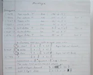
I made all new stringers and formers using the old parts from my plane as patterns well before I had the CD from NAA. This first photo has all the dimensions I recorded. I checked these against the drawings and they're near perfect. As I said before if you end up with a short upper or side stringer that's maybe 1/4", 1/2" or even 1" short on the aft end no one will ever notice.
Photo 2 from overhead showing how the stringer is sanded and fits down flush with the very front cross piece.
Photo 3 same thing from straight on like looking through the windshield showing how it sits flush. All the staple holes are from the headliner and the front end of the fabric.
Photo 4 shows the T stringer sitting above the middle cross piece.
Photo 5 show how the side stringer and side former meet at the TE. Pieces are not finalized yet and not bolted down to meet better.
Photo 6 Same joint from below showing the angle of the wood meets the tubing. Get it close and not too much of a bump, remember all will be covered by the wing root fairings.
Photo 7 belly stringers.
Oh, on what you call the upper deck the old part was 2 3/4" tall at its tallest point at the 2nd cross piece, on the new part I made it 3" tall. Time will tell if it looks right after fabric time.
I made some photos larger so you can enlarge them by clicking on the + sign at the top right.
 

Attachments

  • IMG_4008 (1280x1035).webp
    IMG_4008 (1280x1035).webp
    69.3 KB · Views: 16
  • IMG_4000 (1024x693).webp
    IMG_4000 (1024x693).webp
    38.5 KB · Views: 14
  • IMG_4001 (1024x683).webp
    IMG_4001 (1024x683).webp
    64.2 KB · Views: 11
  • IMG_4003 (1024x683).webp
    IMG_4003 (1024x683).webp
    35.9 KB · Views: 13
  • IMG_3997 (1024x683).webp
    IMG_3997 (1024x683).webp
    58.6 KB · Views: 12
  • IMG_3998 (1024x635).webp
    IMG_3998 (1024x635).webp
    36.5 KB · Views: 11
  • IMG_4005 (1280x853).webp
    IMG_4005 (1280x853).webp
    49.5 KB · Views: 11
Last edited:
Thanks for the great photos and dimensions. I wish I had your expert help when the partner I started with could no longer continue due to health. With your help, I can see how all of this will flow together. The stringer on the right side was split at the T intersection between the upper portion (half-round) and the lower T section. I am not sure how much stringer I have at the other end to push forward. I am not sure if this stringer part is under stress. If the part is not under stress, is it possible to glue the T and the top together and then add a supportive piece where the stringer bolts to the frame?
 
There's quite a bit of stress in those T stringers. So, if you can glue it, then soak it real good and slowly bend it into shape and tie it down with whatever and let dry that may work. A doubler to strengthen it may work, remember everything adds weight, keep it light.

Photo1 here front right corner, you may want to shave a little off the bottom corners at the welds so the whole cabin assembly sits down all the way on the fuselage tubing. You only need a 1/16" or so.
I'm no expert here just learning as I'm going.
 

Attachments

  • IMG_4007 (1024x635).webp
    IMG_4007 (1024x635).webp
    44 KB · Views: 14
Thanks, I made a wood piece for holding the stringer (top and Bottom) so I can apply pressure while gluing the stringer together. After it dries, I will turn the stringer around (place the repaired stringer end at the tail) and bend the new front end into shape because I do not think the pressure past the last former will be as great as the pressure close to the fuselage cabin. Your pictures have been a real Godsend! There are some Aeronca’s on the field but no one that I have found has actually built or repaired them. The stringers are only rough sanded enough to get them into the ¼ inch slots at the formers. I thought the addition of water and bending would make the wood swell and be more work if I sanded, soaked and then shaped but I am not sure. You said “The two upper side formers (what you call an upper deck) should be level with the wing ribs.” How will I know if the side formers are level with the wings?
 
I too thought there might be swelling after soaking the stringers but they fit right in the slots.
I don't know if you have the old parts to use as patterns on the side formers. If you have an old rib to hold up to the fuselage and mark the top of the sides. Your goal is to try and be level from the butt rib to the top sides of the cabin, the fabric may shrink that down a bit too. Figure out a way to do that. It's not rocket science, it doesn't have to be exact, but it looks better afterwards. Remember it will be covered by the wing root fairings too. Just get it close so it's not too low.
The top two center stringers are raised above the rest of the wood and the cabin slopes down to the sides and back.
This is Bill Pancakes Champ, he's the guru of Aeroncas and he knows how to do it right.
 

Attachments

  • Oshkosh 05 131 (1216x1280).webp
    Oshkosh 05 131 (1216x1280).webp
    161.3 KB · Views: 10
Last edited:
Thanks, I will not let the soaking slow me down then. I did not have any wood stringers or formers in the pile of things that came with the airframe. Do you happen to have the dimensions for the bottom rear stringer? I do not have the blueprint for it and I am not sure about how far forward and rear the stringer continues after the 3/16 (1/4 inch) hole that holds it in place. Also is there a slope to the ends of the piece. Thanks again for all your help.
 
I have all the dimensions for the stringers, I just need to know exactly which one you're talking about. Bottom as on the belly, or bottom side?
Or a rough drawing might do.

Edit,
Looking further, I already sent a photo of all the dimensions of the stringers on that paper list. Tell me what stringer you need clarification about the taper at the end.
 
Last edited:
Back
Top