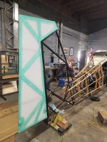
1977 Super Decathlon 8KCAB Rebuild

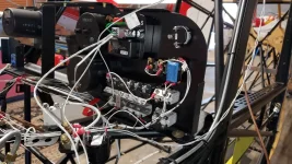
Backside (frontside?) of the panel, started wiring and figuring out the remaining details. The basis for the set up is the ACA electrical system drawing that I purchased from the factory combined with the schematic in the parts manual for my '77. The main power feed from the alternator/battery side of things will attach at the crossover links the two bus bars and then power will exit out the top of the upper switch breakers and CB's and also out the bottom of the lower CB's. The factory set up is very similar, just different for the specific equipment that they'd put in a new plane like a Garmin G3X which I'm not using.

By the way, all of this work uses up way more wire than you'd guess when you're first ordering stuff!

20220424_114135.jpg
 
Last edited:
Backside (frontside?) of the panel, started wiring and figuring out the remaining details. The basis for the set up is the ACA electrical system drawing that I purchased from the factory combined with the schematic in the parts manual for my '77. The main power feed from the alternator/battery side of things will attach at the crossover links the two bus bars and then power will exit out the top of the upper switch breakers and CB's and also out the bottom of the lower CB's. The factory set up is very similar, just different for the specific equipment that they'd put in a new plane like a Garmin G3X which I'm not using.

By the way, all of this work uses up way more wire than you'd guess when you're first ordering stuff!


View attachment 5043

That's great work! I really like your bus bar. Super clean. Would love to renovate my switch panel.
 
That's great work! I really like your bus bar. Super clean. Would love to renovate my switch panel.

It's been a labor of love! It was all a blank canvas and little by little, and with a lot of help from Dale and Chad at ACA and everyone here, it came together. Thanks!
 
Last edited:
Started ordering firewall-forward stuff this past week as I'm almost done with my for-fabric-practice horizontal stabilizer. It's been very educational learning the adhesive and fabric behavior and making sure I've got all of the steps down. ACA sent me fabric tapes but their spec calls for fiberglass tapes so I've got a call out to Dale to clarify and I'll be getting started with the tailfeathers this week then on to the fuselage. A big part of the project has been trying to prep for the next step as the current step (or steps) gets done so I'm on to planning the firewall-forward install now that I'm ready to get the fabric done.

AirGizmos completed development of their iPad Mini 6 panel mount and one is on its way to complete the panel.

With the Citabria tentatively sold, all of the parts for completion are funded, Pat at ACA is generating a labor estimate so that'll be the last piece of the puzzle before moving things along to their final destination!

Pics when the fabric fandango gets started!
 
Looking good, let me share a mistake I made, if you have a rudder tab mark where the screw holes are. This was a failure on my part and after the paint they are invisible. So I’m going to play hide and seek till I find them. I bought a envelop for body and where the rudder goes up the tail I ended up splitting the fabric because I didn’t like the way it was laying down before shrinking.
 
That, and after the sealer and before final taping, assemble a little bit, run the cables, set the slot at the exact center of the cable, then glue on whatever you will use for cable protection. Don't forget the trim cables!
 
Thanks for the replies. here's the plan going forward, let me know what you think.

I need to scuff and touch up the one horizontal stab and elevator panel that I have on hand (panels for the other side are on their way from ACA since I didn't like what I had on hand when I really started looking at them) since the shop that did them didn't do such a great job. It's been too hot to paint though so I started with the rudder. While I wait for a cooler day I'm going to do the bottom fabric on the fuselage. Once that's done I can do final installs of the battery tray and associated wiring, the rear floor board section, and the fuselage controls/cables. With the cables in place I can map out the locations of the rudder and elevator trim cables and plan where the exits will be. from there I can do the side/top fabric panels although I'll probably wait until after the four horizontal stab and elevator panels are done.

Chad sent me the exit points for the rudder cables
The metal grommets are part number 1-9971 and the fabric patches are part number 1-10245

20220803_084531.jpg
 
Last edited:
Looking good, let me share a mistake I made, if you have a rudder tab mark where the screw holes are. This was a failure on my part and after the paint they are invisible. So I’m going to play hide and seek till I find them. I bought a envelop for body and where the rudder goes up the tail I ended up splitting the fabric because I didn’t like the way it was laying down before shrinking.

I bought the rudder new from ACA so there weren't any holes for the trim tab but thanks for the reminder to locate and drill a few! Or maybe I'll leave that for the factory guys when they're installing the wings. :unsure:
 
finished up the rudder last night, was probably 12 hours start to finish!
Are you mounting the GPS on the rear plane and the comm antenna on the front plane? Any differences in performance with that configuration instead of vice versa?
 
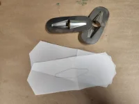
I double checked with Dale, the newer ground plane & antenna mount is for the Comm antenna. The old ground plane, which I think was actually where the rotating beacon was mounted, will be repurposed for the GPS antenna. To actually be a ground plane the old mount has to be grounded to the airframe which it currently isn't so I'll add that to the list.
 
I double checked with Dale, the newer ground plane & antenna mount is for the Comm antenna. The old ground plane, which I think was actually where the rotating beacon was mounted, will be repurposed for the GPS antenna. To actually be a ground plane the old mount has to be grounded to the airframe which it currently isn't so I'll add that to the list.

No rotating beacon on my '78. Comm antenna was on the rear plane. Curious that it would work better on the forward plane, but I understand very little about antenna performance.
 
I double checked with Dale, the newer ground plane & antenna mount is for the Comm antenna. The old ground plane, which I think was actually where the rotating beacon was mounted, will be repurposed for the GPS antenna. To actually be a ground plane the old mount has to be grounded to the airframe which it currently isn't so I'll add that to the list.
A GPS antenna doesn't need a ground plane...it does however need to be mounted away from comm antennas.
Chris
 
A GPS antenna doesn't need a ground plane...it does however need to be mounted away from comm antennas.
Chris

Can 2 GPS antennas be mounted in proximity to each other?

The comm antenna on the forward plane puzzles me a bit. Seems like it would get masked by the wings, whereas the dorsal plane would be less so.
 
A GPS antenna doesn't need a ground plane...it does however need to be mounted away from comm antennas.
Chris

i'm pretty sure i saw in the transponder install manual that the ground plane has to be grounded but i'll look it up later when i get home
 
I use the little Garmin handhelds, with the remote antenna mounted on the tube above the passenger's left shoulder. Never have a drop-out, and I shoot practice ILS approaches using the Garmin as primary all the time. More accurate than the KN53.

Yes, ground planes must be grounded to the shield of the antenna coax. That is the one place where a shield gets grounded at both ends.
 
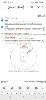
the page from the transponder install manual. the GPS antenna supplies its signal to the Garmin GTX345 transponder. no requirement for grounding of the ground plane to the airframe, @Hiperbiper erbiper gets the square! :)

Screenshot_20220804-123813_Samsung Notes.jpg
 
Back
Top